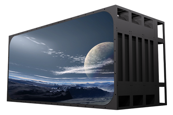
Let the wildest ideas become a visual feast within reach! As an innovative leader in the field of LED display, Meiyad focuses on creating special-shaped LED display solutions that break through conventions.
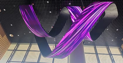
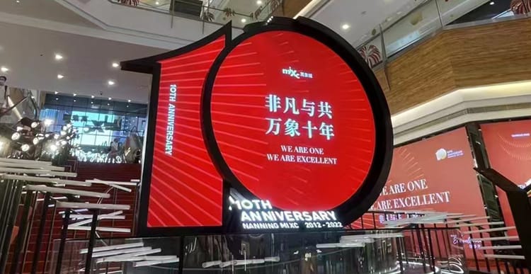
Meiyad stands at the forefront of creative customized LED screen innovation, delivering globally acclaimed projects that merge cutting-edge technology with creative vision. Renowned for tackling complex design challenges, Meiyad has executed landmark installations such as the 70th National Day Hubei Float, MixC Nanning's 10th Anniversary.
Meiyad's Company News showcases our dynamic LED journey – from cutting-edge product launches to employee-driven initiatives. Stay updated on global expansion milestones, team achievements.

Access detailed product catalogs, technical specifications, and installation guides. Download instantly via secure portal. Available 24/7 for global clients.

Shenzhen Meiyad Optoelectronics Co., Ltd. was founded in 2011, national high-tech enterprise which is focusing on R&D, manufacturer, sales and service of LED display. Four production bases in Shenzhen, Hubei, Guangxi and Sichuan, more than 600,000sqm and more 3,500 employees.